
ADIAD8436高精度RMS到DC转换解决方案
ADI公司的AD8436是新一代跨导线性的高精度低功耗真正的RMS/DC转换器,它能精确计算交流波形的rms值,包括由开关电源和TRIAC所产品的复数项。精度优于0.5%,输出失调小于10uV,波峰因素(CF=1-10)时的误差小于0.5%,输入范围满刻度为100 μV rms 到3 V rms (8.5 V p-p),双电源电压为 ±2.4 V到±18 V ,单电源电压为4.8 V 到36 V,主要用在遥控,手持仪表,板空间受限和户外环境的电源和汽车。本文介绍了AD8436主要特性,功能方框图,RMS核方框图,波峰因素测试电路图,典型应用电路以及AD8436-EVALZ评估板电路图和PCB布局图。
The AD8436 is a new generation, translinear precision, low power, true rms-to-dc converter that is loaded with options. It computes a precise dc equivalent of the rms value of ac waveforms, including complex patterns such as those generated by switchmode power supplies and triacs. Its accuracy spans a wide range of input levels and temperatures. The ensured accuracy of ≤±0.5% and ≤10 μV output offset result from the latest Analog Devices, Inc., technology. The crest factor error is 0.5% for CF values between 1 and 10.
The AD8436 delivers instant true rms results at less cost than misleading peak, averaging, or digital solutions. There is no programming expense or processor overhead to consider, and the 4 mm × 4 mm package easily fits into those tight applications.
On-board buffer amplifiers enable the widest range of options for any rms-to-dc converter available, regardless of cost. For minimal applications, only a single external averaging capacitor is required. The built-in high impedance FET buffer provides an interface for external attenuators, frequency compensation, or driving low impedance loads. A matched pair of internal resistors enables an easily configurable gain-of-two or more, extending the usable input range even lower. The low power, precision input buffer makes the AD8436 attractive for use in portable multi- meters and other battery-powered applications. The precision dc output buffer offers extremely low offset voltages, thanks to bias current cancellation.
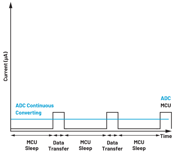
Unlike digital solutions, the AD8436 has no switching circuitry limiting performance at high or low amplitudes (see Figure 2). A usable response of 100 μV and >3 V extends the dynamic range with no external scaling, accommodating the most demanding low signal conditions.
The AD8436 operates from single or dual supplies of ±2.4 V (4.8 V) to ±18 V (36 V). A and J grades are available in a compact 4 mm × 4 mm, 20-lead chip-scale package. The operating temperature ranges are −40°C to 125°C and 0°C to 70°C.
The AD8436 is a good choice for remote, portable battery-powered instrumentation, energy and automotive applications where limited board space and outdoor environments are considerations.
AD8436主要特性:
Computes true rms value instantly
Accuracy: ±10 μV ± 0.5% of reading
Wide dynamic input range
100 μV rms to 3 V rms (8.5 V p-p) full-scale input range
Larger inputs with external scaling
Wide bandwidth:
1 MHz for −3 dB (300 mV)
65 kHz for additional 1% error
Zero converter dc output offset
No residual switching products
Specified at 300 mV rms input
Accurate conversion with crest factors up to 10
Low power: 300 μA typical at ±2.4 V
Fast settling at all input levels
High-Z FET separately powered input buffer
RIN ≥ 1012 Ω, CIN ≤ 2 pF
Precision dc output buffer
Wide supply range
Dual: ±2.4 V to ±18 V
Single: 4.8 V to 36 V
Small size: 4 mm × 4 mm package
ESD protected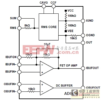
图1。AD8436功能方框图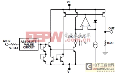
图2。AD8436 RMS核方框图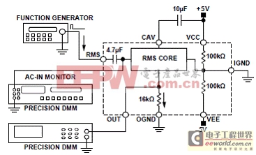
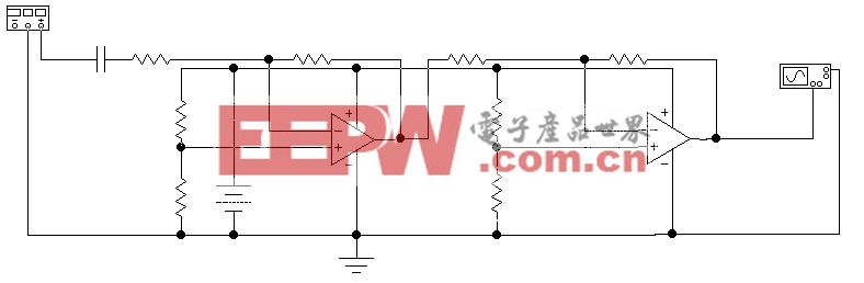
图3。波峰因素测试电路图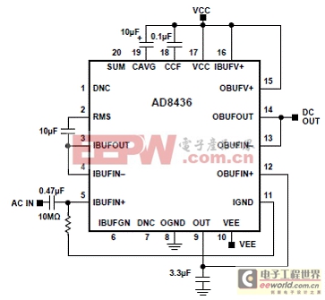
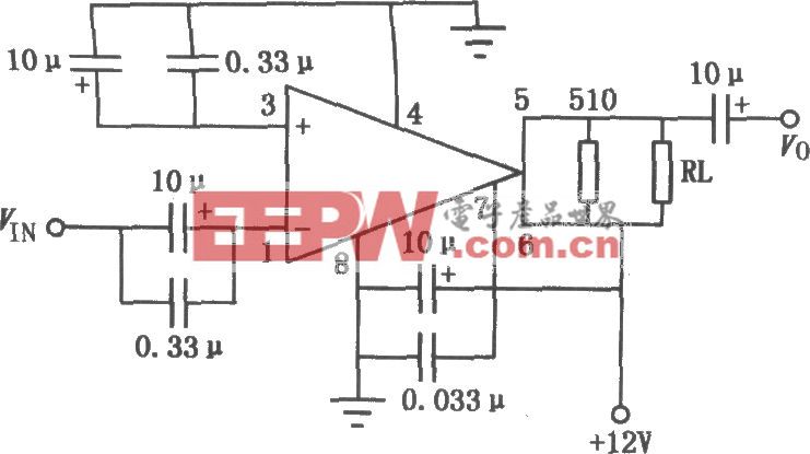
图4。AD8436典型应用电路
AD8436-EVALZ评估板
The AD8436-EVALZ provides a platform to evaluate AD8436 performance. The board is fully assembled, tested and ready to use after the power and signal sources are connected. Figure 45 is a photograph of the board. Signal connections are located on the primary and secondary sides, with power and ground on the inner layers.
The AD8436-EVALZ offers many options, without sacrificing simplicity. The board is tested and shipped with a 10 μF averaging capacitor (CAVG), 3.3 μF low-pass filter capacitor (C8) and a 0.1 μF (COPT) capacitor to optimize crest factor performance. To evaluate minimum cost applications, remove C8 and COPT.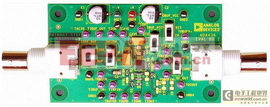
图5。AD8436-EVALZ评估板外形图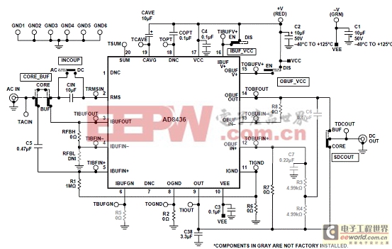
图6。AD8436-EVALZ评估板电路图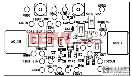
图7。AD8436-EVALZ评估板元件布局图
详情请见:
http://www.analog.com/static/imported-files/data_sheets/AD8436.pdf


评论